
Installation Guide
Introduction
Thank you for purchasing our product! Your support is very important to us! You made a right choice into making your swamp cooler smart!
Core benefits of using swamp/evaporative cooler over traditional AC:
Fresh Air. The air is coming from the outside instead of recirculating the air
Filtered Air. The pads (towels) on your evaporative cooler not just cool but act as a filter as well
Moist Air. Chances are if you are using evaporative cooler – you are living in a dry climate. Your evaporative cooler acts as a free of charge dehumidifier which is good for your skin and wellbeing
Airflow. Since swamp coolers are using the air from outside you have to open windows/doors to create airflow. It is a simple way to control the cooling areas and it feels good!
Low Operating Cost. Evaporative cooling is simple, cheap and effective. Running traditional AC can be 5x to 10x more expensive.
Thank you for making your home smarter, greener and more efficient! Now, that is smart!
Word of Caution
The high voltage wiring and circuits bring the hazard of severe electrical shock or burn!

Disconnect electric power to the system at the main fuse or circuit breaker box prior to the installation! Do not hesitate to hire an electrician or qualified HVAC specialist to perform the installation if you are not familiar (or comfortable) with AC electric systems and residential wiring concepts.
Hardware, PCB & Schematic Overview

Hardware Overview

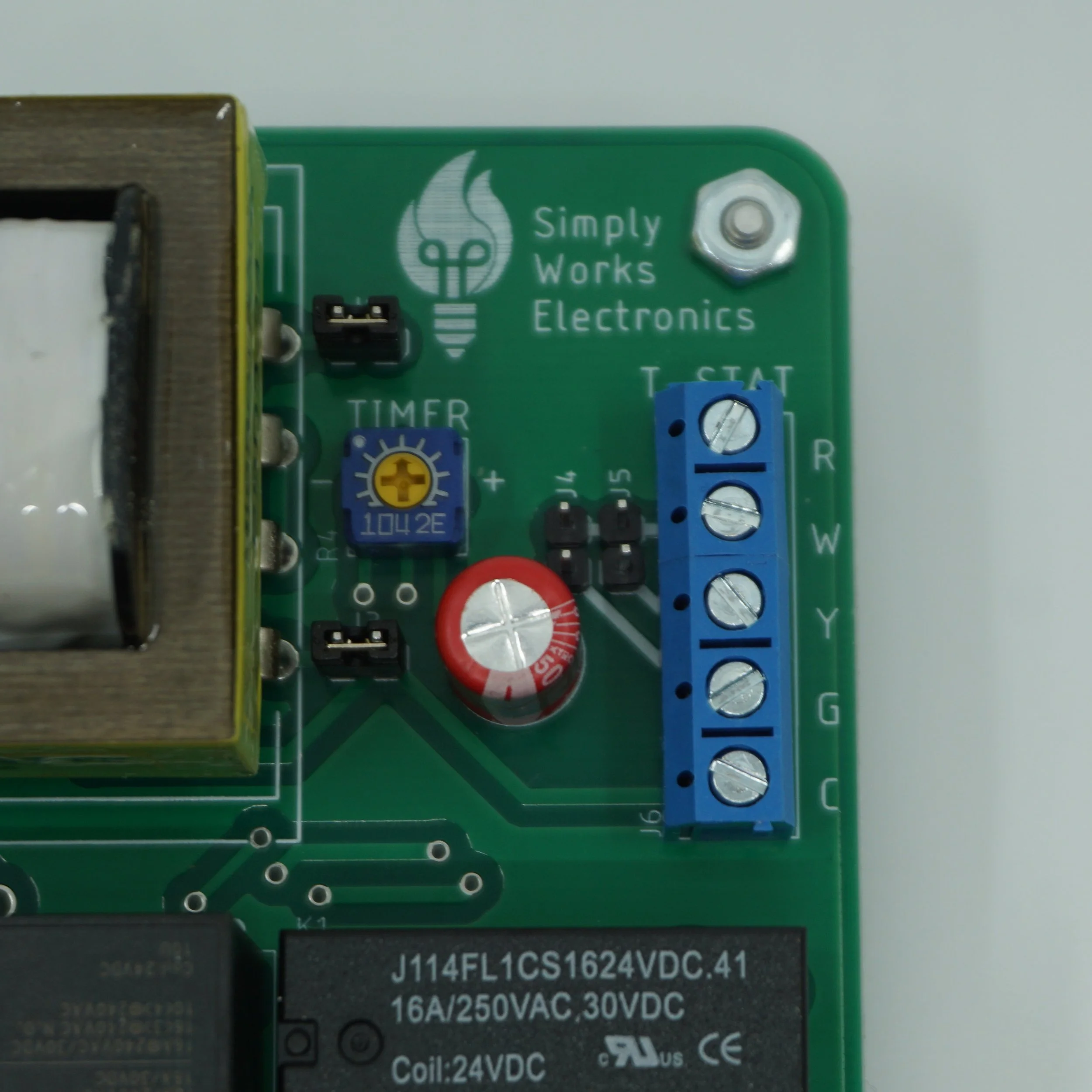
Printed Circuit Board Overview

Simplified Schematic
-
● Smart Swamp Cooler PCB
● 4 x standoffs
● 4 x flathead machine screws
● 4 x hex nuts
● 2 x thermostat jumpers
● Enclosure (Optional)
● 4 x drywall anchors (Optional)
● 4 x mounting screws (Optional)
● 3 x knockout push in connectors (Optional)
● 1 x grounding screw (Optional)
-
● Wire stripper
● Needle nose pliers
● Multimeter
● Electrical tester
● Set of screwdrivers
● Drill
-
● Romex cable(s) for the evaporative cooler side
● Thermostat cable for the thermostat side
Make a Plan
Plan accordingly, we recommend placing Smart Swamp Cooler unit in either an attic or a crawl space depending on the location of the swamp cooler.
You might choose to purchase an enclosure from us. If that is the case, we will send out supporting mountain hardware for the enclosure. The enclosures that we sell have NEMA 1 rating. Meaning that those were designed for the indoor environment and can protect from light, dirt, and outside contact. Do not place enclosure outdoors or inside swamp cooler assembly unless it is rated for those environments!
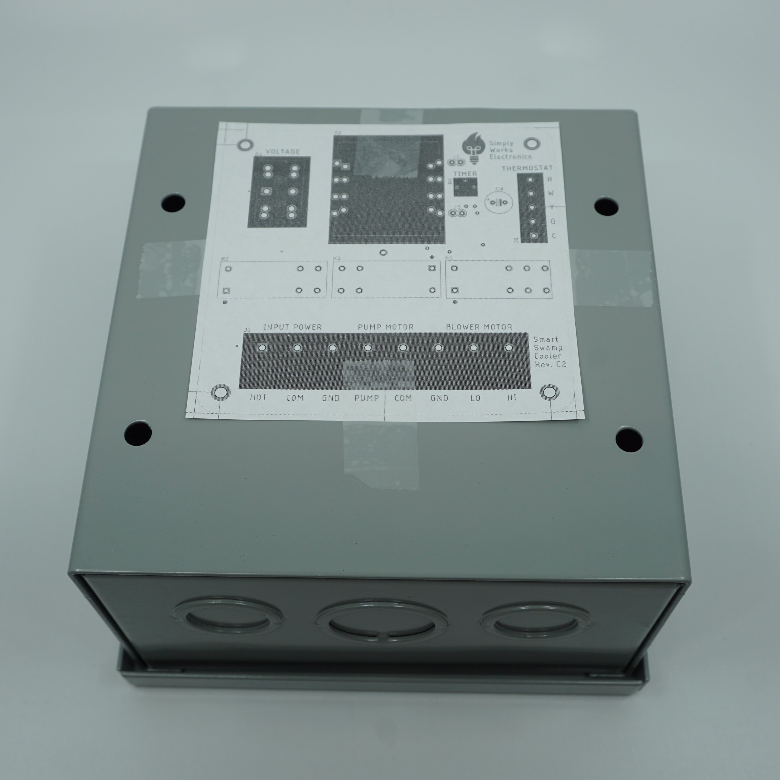
No matter what enclosure you choose, we will send out a mounting template that you can use to drill the mounting holes in your enclosure. We recommend 1/8” drill bit for the task. Please remove all of the drilling debris after drilling.
-
You may choose any enclosure you please. Remember, the rough dimensions of the PCB are 4 × 4 × 1.5 inches.
If you are after outdoor install or install inside a swamp cooler assembly, we would suggest using waterproof junction box such as one of those 2 from Amazon:If you are doing in-wall install, you might want to use something like Steel City junction box. Remember, this is a pretty tight fit!
For the attic or indoor install that have a bit more space, one of those enclosures would probably do wonders:
-
Use a Romex cable that can carry higher voltage and current for the evaporative cooler connections. We recommend using 14/2 and 14/3 or 12/2 and 12/3 cables or 12/2/2 cable if you want to combine pump/motor signals into a single cable.
Use a thermostat cable for the thermostat connection. We recommend 18/5 but you might use less signals if you are going for simple on/off functionality.
-
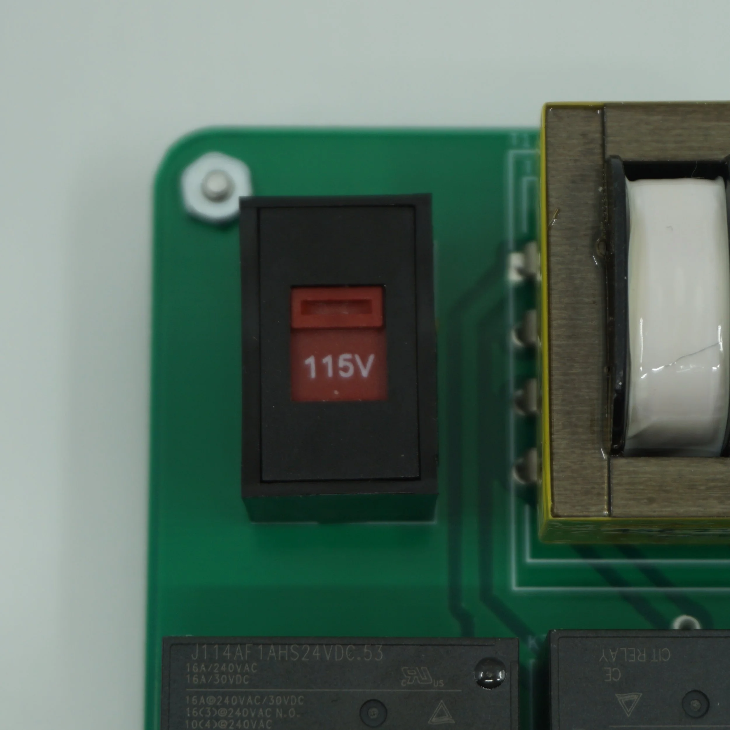
Consult your evaporative cooler manual to identify pump, blower motor, common and ground connections. Also note the operating voltage of your swamp cooler. Use the voltage selection switch on the Smart Swamp Cooler PCB to select appropriate voltage.
If your evaporative cooler operates in the range of 110-120V, select 115V mode on the switch. If your evaporative cooler operates in the range of 220-240V, select 230V mode on the switch.
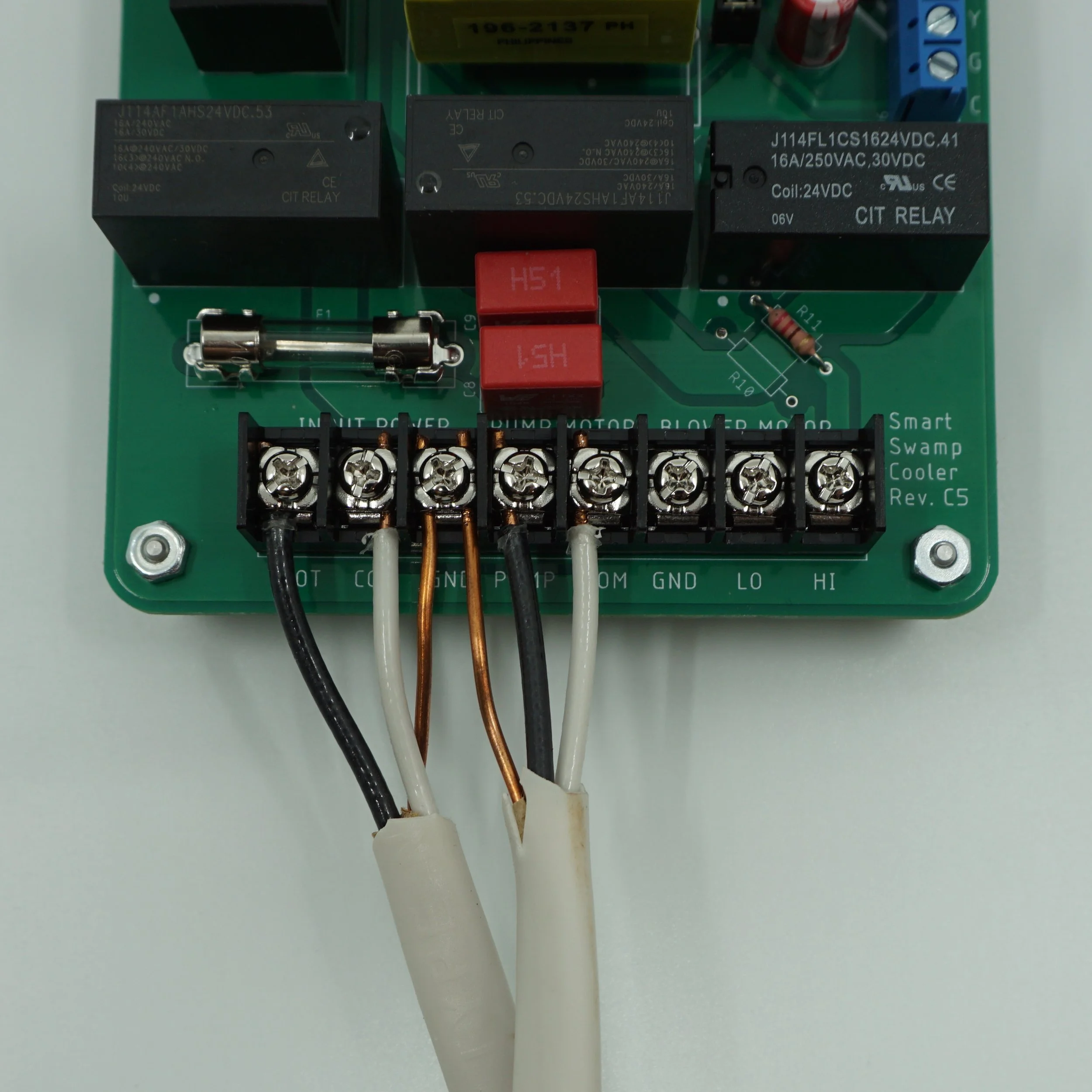
Once again, make sure the power is off and let’s begin wiring. Wire following connections on the controller PCB:
incoming high voltage power cable
pump
low and high blower motor connections
For each bullet point, wire all the common (neutral) and hot connections. You might have only a single COM connection for both pump and blower motor or you might have separate COM connections for those 2. You may use any COM connection on the printed circuit board. Those are connected internally. The latest revision of the Smart Smart Cooler PCB will have 2 GND connections. Those are internally connected so you can use either/or. Furthermore, the standoffs are electrically connected to GND as well. Those will ground your enclosure. Alternatively, you may use a ground bump on the enclosure for an extra grounding of the enclosure.
At this time, you may adjust the timer circuit. Use a Philips screw driver to set the potentiometer. The left most position corresponds to 3 seconds. The right most position corresponds to 90 seconds. The middle is about 45 seconds. Consult your evaporative cooler manual to decide on the optimal presoak timing.
-
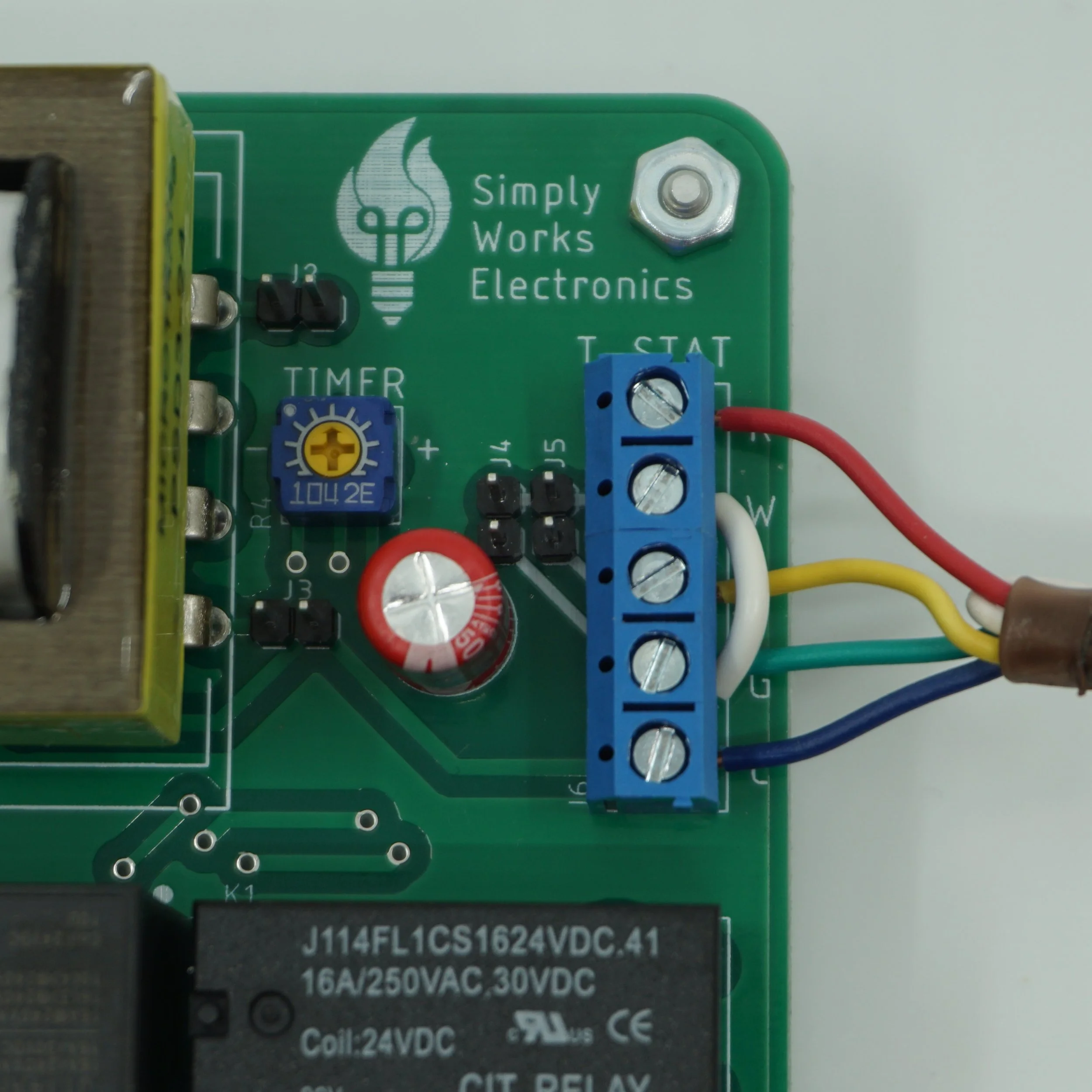
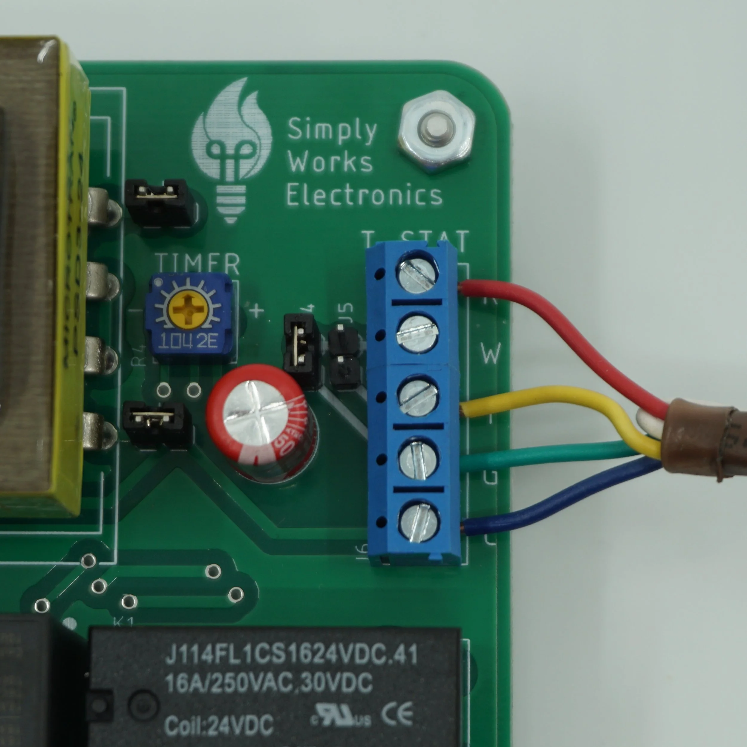
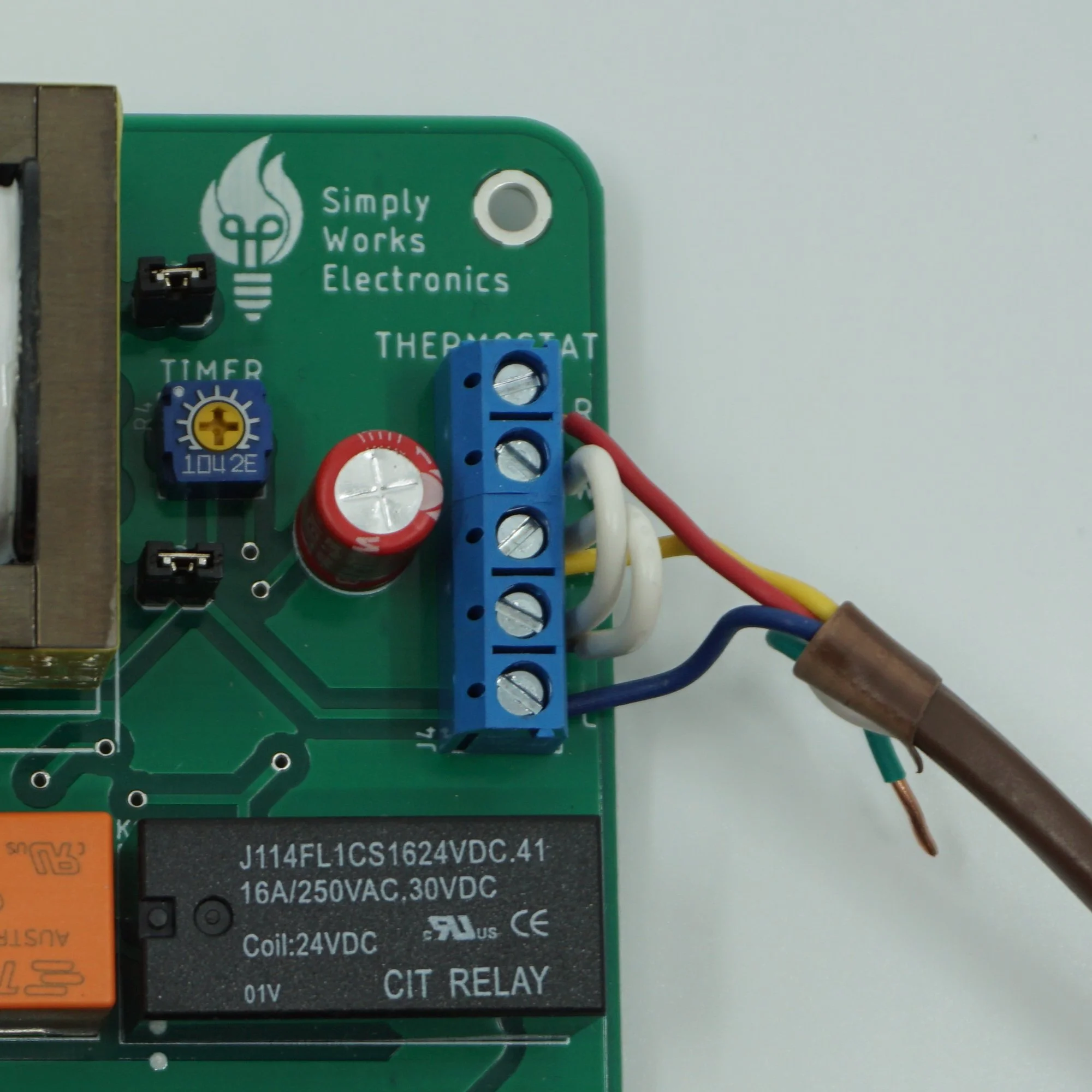
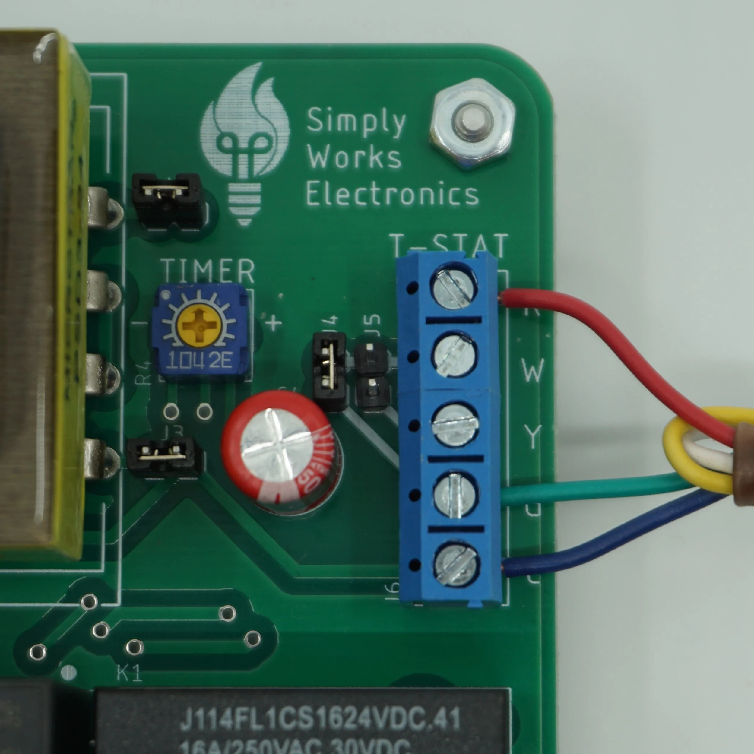
Wire the thermostat connections. Here is the thermostat connection description:
● R - 24 VAC power
● W - Pump Relay
● Y - Blower Motor High Speed Relay
● G - Blower Motor Relay (Timer Relay)
● C - 24 VAC common wire
Most likely you won't be connecting all of the signals to your thermostat. It is possible to connect all of them if you have a dedicated thermostat for the evaporative cooler.
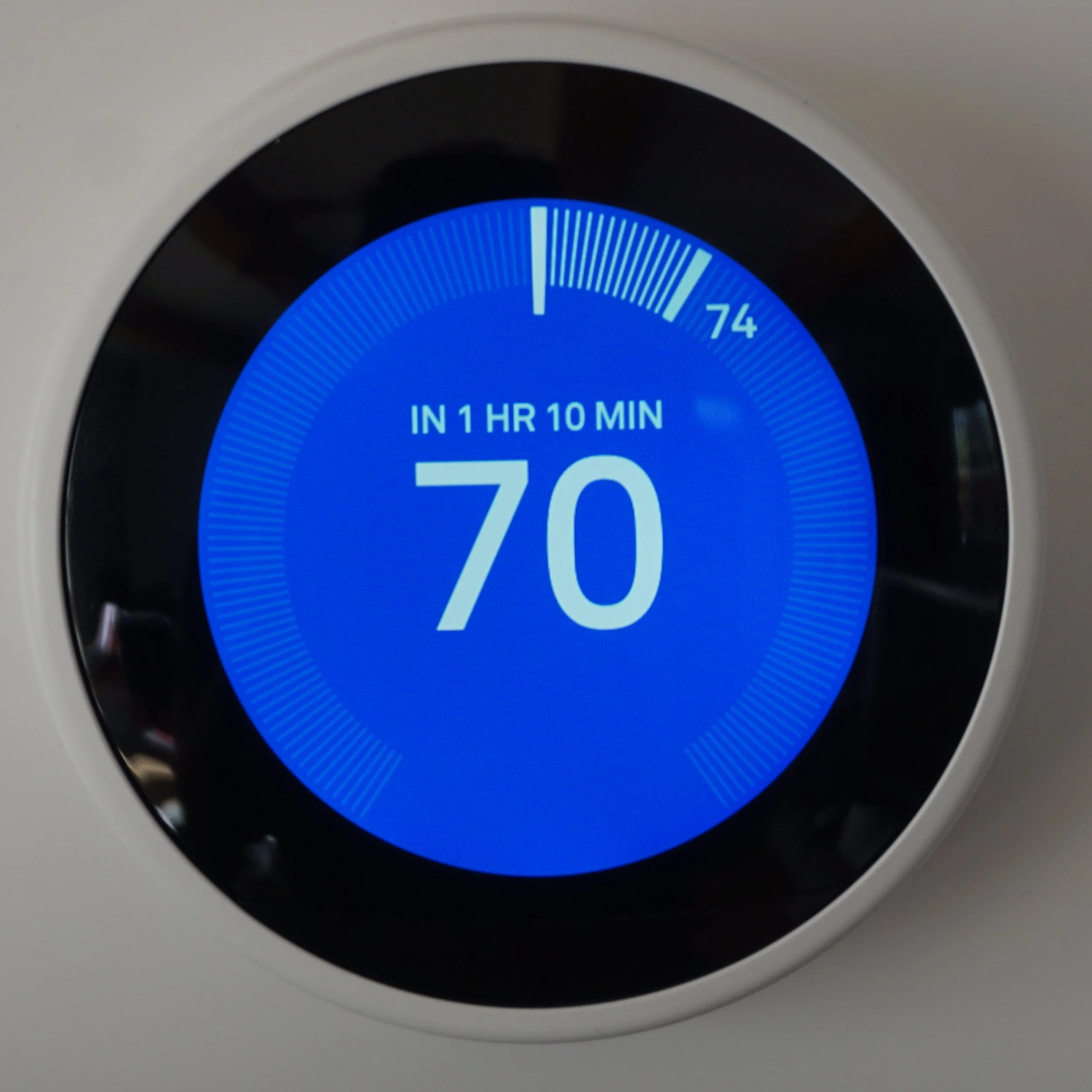
In this manual, we will be using Nest learning thermostat (3rd generation). But you should have similar signal conventions on your smart thermostat. Nest learning thermostat has Y1, Y2, G, Rc, C, Rh. C, Rc and Rh are power signals. To get a better idea what you are working with, consult your smart thermostat manual or better yet review your current thermostat connections. Check if you have C/Rh connected from the furnace. If you do that means that your thermostat is powered by the furnace.
The Smart Swamp Cooler PCB has its own transformer and therefore its own Rc and C pair. The power pairs coming from the furnace and the cooling side are powered by 2 different transformers so there is a risk of damaging your equipment by tying those together! If you opt out for the dual transformer setup, you will have to connect R coming from the Smart Swamp Cooler to the Rc signal. Disconnect C wire coming from the furnace and connect C wire coming from your cooler. Once again, do not tie the common wire from the cooler to the common wire from the furnace in this configuration! Do not tie Rc and Rh! You might opt out for the single transformer setup if you decide that makes more sense.
Next, check if the G connection is occupied by the furnace. If it is not connected, you can connect G from the evaporative cooler. That will run the evaporative cooler fan when you decide to run the fan only using your thermostat. However, we think it makes way more sense to use this signal by the furnace rather than an evaporative cooler or not use it at all. If you do decide you need this functionality, we suggest to follow a single transformer setup instead.
The most common setup that we anticipate is wiring 4 signals - Rc, Y1, Y2, C. Connect W and G at the PCB, connect the resulting G signal to Y1 at the thermostat, and finally connect Y to Y2. Refer to Solution B or C below. If your thermostat has only one stage cooling control (single Y), decide for yourself if you want to run cooling always on high or low. If you want to run it on high, connect W, Y, G at the Smart Swamp Cooler board and connect the resulting Y to Y at the thermostat (Solution D). Otherwise, connect only W and G and connect the resulting G signal to Y1 on the thermostat side. (Solution E)
Yet another option is to disable swamp cooler transformer and drive relays using furnace transformer (Solution A). To enable this option, you must remove transformer jumpers from Smart Swamp Cooler PCB.

Transformer Jumpers

Ready to wire?
TLDR aka Installation Guide Illustrated
-
![Breaker Box]()
Step 1
Turn off cooler/furnace at the breaker
-
![]()
Step 2
Attach template to the box
-
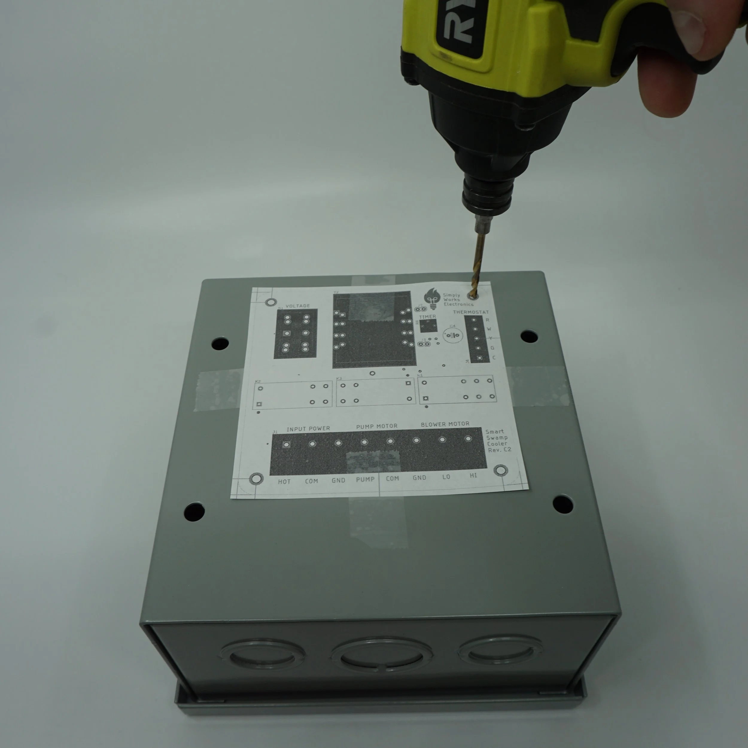
![]()
Step 3
Drill mounting holes using 1/8” bit.
Remove debris
-
![]()
Step 4
Install standoffs
-
![Attach Enclosure]()
Step 5
Attach Enclosure
-
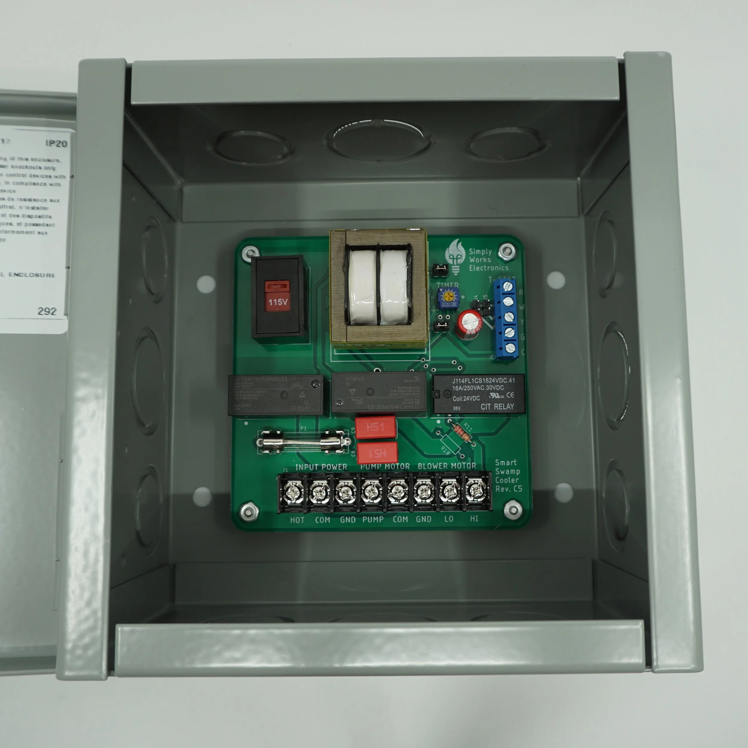
![Attach the PCB]()
Step 6
Attach the PCB
-
![Voltage Selection]()
Step 7
Select Power Input Voltage
-
![Timer Selection]()
Step 8
Adjust the Timer
-
![Incoming Power Connection]()
Step 9
Connect Incoming Power
-
![Pump connections]()
Step 10
Connect Pump
Note: Your wiring might differ from pictured
-
![Blower Motor Connection]()
Step 11
Connect Blower Motor
Note: Your wiring might differ from pictured


Review your Thermostat Wiring

Option 1 - Most Common Setup
Would you like your furnace fan to circulate air while the swamp cooler is on?
If YES continue to
Solution A: Single Transformer Setup
Pros: More flexible setup Cons: A bit more wiring
NO? But still want to run the fan on its own during heating?
Solution B: Dual Transformer, 2 stage heating
Pros: Less wiring Cons: Only possible if you have a W2 signal
Don’t care about the fan only option?
Solution C: Dual Transformer, no G wire
Pros: Even less wiring! Cons: Can’t run fan on its own
Missing Y2 or W2 signals?
Solution D: Dual Transformer, 2 wire setup
Pros: The least wiring! Cons: Single stage heating/cooling
Note: Solutions B/C/D, use C wire from the cooling side!
Disconnect C wire from the furnace side.

Option 2 - Missing C wire
Would you like your furnace fan to circulate air while the swamp cooler is on?
If YES continue to
Solution A: Single Transformer Setup
Pros: More flexible setup Cons: A bit more wiring
NO? But still want to run the fan on its own during heating?
Solution B: Dual Transformer, 2 stage heating
Pros: Less wiring Cons: Only possible if you have a W2 signal
Don’t care about the fan only option?
Solution C: Dual Transformer, no G wire
Pros: Even less wiring! Cons: Can’t run fan on its own
Missing Y2 or W2 signals?
Solution D: Dual Transformer, 2 wire setup
Pros: The least wiring! Cons: Single stage heating/cooling
Note: Use C wire from the cooling side!

Option 3 - Missing G wire
No G wire? No problem!
Want to use fan only option for the swamp cooler’s fan control?
Solution F: Dedicated Thermostat
Pros: Using all the signals! Cons: Do not use fan only option during winter
Don’t care about the fan only option?
Solution C: Dual Transformer, no G wire
Pros: Even less wiring! Cons: Can’t run fan on its own
Missing Y2 or W2 signals?
Solution D: Dual Transformer, 2 wire setup
Pros: The least wiring! Cons: Single stage heating/cooling
Want to opt out for the low speed for the swamp cooler?
Solution E: Dual Transformer, 2 wire variation
Pros: The least wiring! Quieter Operation! Cons: Single stage heating/cooling
Note: Use C wire from the cooling side!
Disconnect C wire from the furnace side.

Option 4 - Missing G and C wires
No G wire? No problem!
Want to use fan only option for the swamp cooler’s fan control?
Solution F: Dedicated Thermostat
Pros: Using all the signals! Cons: Do not use fan only option during winter
Don’t care about the fan only option?
Solution C: Dual Transformer, no G wire
Pros: Even less wiring! Cons: Can’t run fan on its own
Missing Y2 or W2 signals?
Solution D: Dual Transformer, 2 wire setup
Pros: The least wiring! Cons: Single stage heating/cooling
Want to opt out for the low speed for the swamp cooler?
Solution E: Dual Transformer, 2 wire variation
Pros: The least wiring! Quieter Operation! Cons: Single stage heating/cooling
Note: Use C wire from the cooling side!

Option 5 - Dedicated Thermostat
The world is your oyster!
Pick ANY solution from above!
OR
Solution F: Dedicated Thermostat
Pros: Using all the signals! Cons: Do not use fan only option during winter
Note: Solution F, heating side is not shown.
Use C wire from the cooling side! Disconnect C wire from the furnace side.
Solution A - Single Transformer Setup
-
![Remove jumpers]()
Step 1
Disable swamp cooler transformer by removing J2 & J3 jumpers
-
![W to G]()
Step 2
Jump W to G using J4 jumper at the PCB
(pump to timer control) -
![W to G Alternative]()
Step 2A
Alternatively,
Jump W to G using wire jumper instead -
![At thermostat]()
Step 3
Connect Y, G, Rc to Rh, Cc to Ch at the thermostat


Solution B - Dual Transformer, 2 stage heating
-
![W to G]()
Step 1
Jump W to G using J4 jumper at the PCB
(pump to timer control) -
![W to G alternative]()
Step 1A
Alternatively,
Jump W to G using wire jumper instead -
![At thermostat]()
Step 2
Move G to W1, W to W2.
Connect Y1, Y2, Rc and C at the thermostat


Solution C - Dual Transformer, no G wire
-
![W to G]()
Step 1
Jump W to G using J4 jumper at the PCB
(pump to timer control) -
![W to G alternative]()
Step 1A
Alternatively,
Jump W to G using wire jumper instead -
![At thermostat]()
Step 2
Disconnect G wire from the G signal (if present)
Connect Y1, Y2, Rc and C at the thermostat


Solution D - Dual Transformer, 2 wire setup
-
![W to G, W to Y]()
Step 1
Jump W to G, W to Y using J4 & J5 jumpers at the PCB
(pump to timer to high motor control) -
![W to G, W to Y alternative]()
Step 1A
Alternatively,
Jump W to G, W to Y using wire jumpers instead -
![At thermostat]()
Step 2
Connect Y1, Rc and C at the thermostat


Solution E - Dual Transformer, 2 wire variation
-
![W to G]()
Step 1
Jump W to G at the PCB
(pump to timer control) -
![W to G alternative]()
Step 1A
Alternatively,
Jump W to G using wire jumper instead -
![At thermostat]()
Step 2
Connect Y1, Rc and C at the thermostat


Solution F - Dedicated Thermostat
-
![No jumper mods]()
Step 1
No jumper modification required
(might want to reduce timer duration) -
![At thermostat]()
Step 2
Connect G, Y1, Y2, Rc and C at the thermostat


Finish Line
-
![Breaker Box]()
Final Step
Turn on cooler/furnace at the breaker
-
![Check your thermostat operation]()
Very Final Step
Finish setting up your thermostat and test the operation
FAQs
What is the difference between neutral and common signals?
It is the same signal! We named those 2 signals differently just to emphasize that one comes from the input power and the other one comes from the evaporative cooler assembly.
Can you provide additional info on Nest wiring signals?
This video is a great resource. Otherwise Nest Pro Installer Guide is very useful as well! Please check it out!
Can you provide more info on Dual vs Single transformer setup?
Yes, please check out this blog post on this topic.
I lost my drilling template. Where can I find those?
You can download those right here. Just find the template corresponding to your revision of the board and print it out using actual size.
What is the difference between neutral and ground signals?
Those are 2 different signals. The neutral signal is the return path for the AC power. The ground signal is a “safety” ground. It is physically tied to ground, the shields of the electrical wiring and enclosures.
The cooling relay does not seem to be working.
The cooling relay has a timer delay. Your thermostat might have a delay as well. 2 delays equals 1 very long delay. Check your thermostat manual to find out if it is possible to adjust the delay. Set timer delay on the Smart Swamp Cooler PCB to a minimum if your thermostat has a built in delay.
Why is the G signal somewhat problematic and what are the possible work arounds with it?
We’ve got some answers. Please check out this blog post on this topic.
My board is not blue as pictured in the manual.
That means you have a different revision of the board. Newer and improved revision!
How can I switch between high and low fan with a thermostat?
Your smart thermostat is supposed to handle that part for you. On the Nest thermostat, it will run at the low speed when the difference between your target temp and current temp is small otherwise it should run on high.
If you want to overwrite this behavior, you could wire the thermostat to do either high or low all the time or even put a mechanical switch to control the speed.
There are also Nest Pro Installer settings that might allow you greater control over your thermostat.